Hull Inspection, Damage and Repair ( Reporting and Assessing Structural Defects ) Part III
Stress Concentrations
Hard Point (more than 80mm from the structure)


SOLUTIONS:

End of Bracket


Misalignments


Three Planes


Stress concentrations occur at any discontinuity in the structure with an intensity related to the abruptness of the change. For convenience, areas of stress can be divided into the following seven types.
Hard Point (more than 80mm from the structure)
The hard spot (or hard area) can be defined as:
- a point (or area) locally rigid in a flexible or less rigid structural element.
- also as a point (or area) where the deflection curve of a plate is
- abruptly interrupted by the effect of a very rigid member supported by the plate.
- as a point (or area) where there is an abrupt change in rigidity.
These abrupt changes in the deflection lines induce high local stresses. In those points (or areas) there is a great possibility to find cracks.
There are 3 types of hardpoints:
Hardpoint Nº 1.
Bracket welded to a plate. Distance to the nearest stiffener >= 80 mm Consequences > Crack perpendicular to the bracket in the plate. Also, it can be caused by a “doubler”.


Hardpoint Nº 2.
End of a face flat in a bracket Consequences > Crack in the bracket plating

Hardpoint Nº 3.
Different deformation, under the same loads = Change of rigidity = Hardpoint
The brackets should not end on unsupported plating.
The corners of trunks should not end on unsupported plating
SOLUTIONS:

The solution, although it may sound trivial, is to avoid or eliminate the hard points or to make a gradual change of rigidity
1) To place a small pad under the bracket toe.
2) To extend the bracket to the next support.
3) To place longitudinal support underneath the bracket.
4) To place transverse support underneath the bracket toe.
In other cases, we have to make the change of rigidity more gradual. Among the many possible solutions, we have to elect the best under the quality/cost criteria.
End of Bracket
The ends of brackets and of stiffeners are prone to fractures and therefore, should be examined carefully.
We can consider three types of more frequent failures:
End of bracket Nº 1) - In this case, the welding connection of bracket or stiffener with the plating is fractured


End of bracket Nº 2)
In this case, the bracket or stiffener breaks the support element


End of bracket Nº 3)
In this case, the bracket or stiffener breaks the support plate.

In addition to three listed above there is also, Bracket Nº4)

In this case, the bracket itself is broken.
SOLUTIONS for End of Bracket
Change of Section
No1

No2

No3

In general, the solution is to modify the shape of the bracket (or to add a new one), although, sometimes, it is necessary to increase the size of the bracket.
In other cases, it will be necessary to extend the bracket to the adjacent stiffener or to incorporate a new stiffener to fix end the bracket.
Change of Section

Change of Section –Solution –Fit bracket

Change of Thickness

Solution – Insert an intermediate thickness
Diminish the thickness difference and make the transition as gradual as possible, in the order of 3:1 or 4:1.
Insert an intermediate thickness plate when the difference in thickness is more than about 1.5-2 times. Otherwise, improve the transition to 4-5: 1 by chamfering *
*A chamfer is a transitional edge between two faces of an object. A form of a bevel, it is created at 45° angle to two adjoining right-angled faces. A lark's tongue is a chamfer which ends short of a piece in a gradual upward curve, leaving the balance as a right angle.
Openings
Case 1

The solution for the photo above is to close the opening.

Case 2

The solution for case 2 – Increase the radius
If a flange is present on the opening ( as above) increasing the flange thickness in addition to increasing the radius will also reduce the stress.
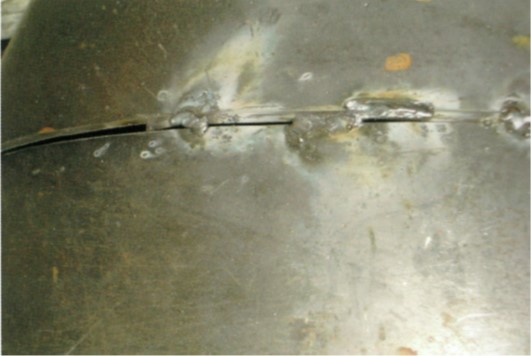
Misalignments


Solution 1- Full penetration weld
Changing the fillet weld to a full penetration weld ( allows better continuity of the stresses through the misalignment.

Solution 2- Thicker insert
A thicker insert will also allow for better continuity of the stresses through the misalignment. Care should be taken to chamfer the ticker plate
to minimise the effect of the change of thickness.
Solution 3 Re –align
Re-alignment of structure in existing ships is never recommended as it will require a great deal of work to disconnect adjoining structure, and will induce other misalignments in the vicinity
Full penetration weld and a thicker insert will always be easier and cheaper.
Three Planes
(crack always on fillet weld)
When the three planes meet, such as at the intersection of a longitudinal and transverse bulkhead with a platform /stringer deck, there is always the possibility of the stress concentration arising at the point where they intersect. This can lead to fractures, although the type of damage depends on the size and type of the ship.


Solution 1 – Fit bracket (no scallop) in line with the plane on the other side


Solution 2 – Close scallops ( where the bracket is already fitted)

Difference Between Hard Points and End of Brackets

References :
- Bureau Veritas (2006). Mini Survey Handbook Part A - Ships in Service. (First ed.). France: Marine Division Ships in Service Management ( DNS).
- Gutierrez, M. – Retired Senior Surveyor LR, 2018. Conversation/Lecture to/with Aleksandar Pudar from 18 to 21/9/2018.
- Lloyd's Register Marine (2014). Hull Inspection, Damage and Repair. (Third Edition ed.). United Kingdom: First published by Lloyd's Register ,2009.
- Lloyd's register marine (2015). Hull Inspection, Damage and Repair. (First ed.). United Kingdom: Lloyds Register.
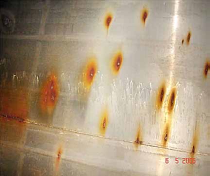
- Researchgate.net. 2018. “ Pitting intensity diagrams” www.ResearchGate.com [Online]. Available from: <https://www.researchgate.net/figure/Pitting-intensity-diagrams-Figure-taken-from-2_fig4_320716318 > [Accessed on : 2 October 2018].
- Marchant , T, Dr.Lomas, J & Dr.Callow, L (2009). WHITE PAPER:THE FEASIBILITY OF A CORROSION RESISTANT SHIP. [Online]. (1 ed.). United Kingdom: © BMT Defence Services Limited 2009 © Amtec Consultants Ltd 2009. Available from: <https://www.bmtdsl.co.uk/media/6098421/BMTDSL-Corrosion-Resistant-Ship-Whitepaper.pdf >[Accessed on : 2 October 2018].
- Tanker Structure Co-operative Forum (1995). GUIDELINES FOR THE INSPECTION AND MAINTENANCE OF DOUBLE HULL TANKER STRUCTURES. (1st ed.). England: Witherby & Co.Ltd.
- Tanker Structure Co-operative forum (2014). Guidance Manual for Tanker Structures - Consolidated Edition 2014. (2nd ed.). Great Britain: Witherby Seamanship International.
- Tanker Structure Co-operative forum (1986). Guidance Manual for the Inspection and Condition Assessment of Tanker Structures. (1st ed.). England: Witherby Marine Publishing.
- Tanker structure co-operative forum (1992). Condition Evaluation and Maintenance of Tanker Structures . (1st ed.). England: Witherby & Co.Ltd.