Hull Inspection, Damage and Repair ( Reporting and Assessing Structural Defects ) Part II
Considerations When Dealing With Damages
Fatigue
These loads are either cyclical or alternating in action.


Age of Ship

Fatigue
- Alternate or cyclic loading
- Loads lower than breaking load and yield stress
The material fatigue can be defined as the failure under alternating fatigue load or the propagation of a fracture due to a load of a cyclic nature.
Items of structure that form part of a ship may fail due to service loads and associated stresses, which are much smaller than the maximum breaking loads and stresses they were designed to withstand.
 |
| Fatigue |
These loads are either cyclical or alternating in action.
In all types of fatigue fracture, crack start because of the concentration of localized stress in the component of the structure.
The fatigue curve
The fatigue curve shows the number of fatigue cycles at given stress before an item fails.
By reducing the stress in a location below the fatigue limit it should not fail again in the service life of the ship.
If a fatigue failure occurs early in the life of a ship the remedial action must be comprehensive in order to reduce the actual stresses to blow the fatigue limit.
If a fatigue failure occurs in a location late in the ship life it may be appropriate simply to repair as per the original design.
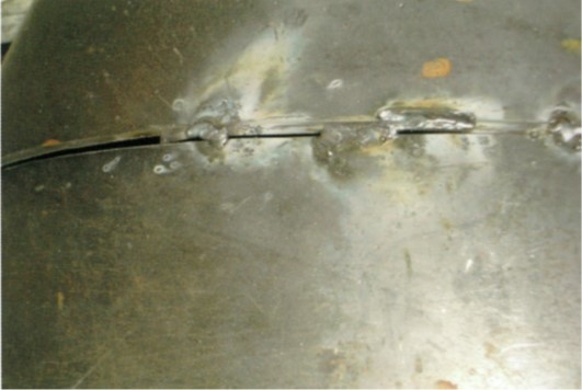
Corrosion Under Stress
Accelerated corrosion will occur where there are high levels of stress. Even within the same space on a ship, corrosion rates at locations of stress concentration will be greater than in those locations where the stresses are lower. This can be seen particularly where sea water is present, such as inside ballast tanks where coatings have broken down.
The “stress cycle”

The acceleration of corrosion is cyclical and self-perpetuating; it occurs because wastage from corrosion leads to more stress on the area and in turn corrosion.
An area suffering from corrosion can rapidly deteriorate if coatings are not repaired or modifications are not carried out on the structure, which will reduce the stresses present.
The stress cycle often produces fracture lines at the point of the highest initial stress. In other cases, the area around the initial stress concentration becomes corroded.
 |
| Corrosion Under Stress |
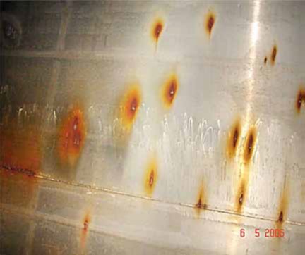
Progress(ive) of Corrosion
Inspections would be simple if the rate of corrosion was linear, however, the real rate of corrosion tends to accelerate over time.
Progressive corrosion

The stress cycle applies here too and once corrosion is established, it will become progressively worse unless preventive action is taken.
Corrosion will continue to develop when:
The coating is not in good condition
The load that the structure is carrying is high; and
There is greater humidity and or higher surrounding temperatures
Solving stress and progressive corrosion :
Recoat protective coatings to stop corrosion
Increase thickness of structural members to reduce stress
Increase the radius of openings to reduce stress
Increase the thickness of flanges used at the opening to reduce stress
Close opening to reduce stress.
Humidity and Heat
In general heat and humidity affects the tanks mostly above the load line.
The only solution to prevent this corrosion is the adequate maintenance of the coating

Higher temperatures and humidity will increase corrosion rates in unprotected environments.
If they are both present, the effect is compounded and the rate of corrosion accelerates rapidly.
Areas on the ship that are most prone to increased heat and humidity ( and therefore to accelerated corrosion) are the tanks above the waterline and those next to heated spaces.
Within a tank, particular attention should be paid to its uppermost part, especially where the tank boundary is exposed to direct sunlight.
Vulnerable tanks:
- Fore and aft peak tanks
- Deep Tanks
- Side tanks
- Tween deck tanks
- Topside tanks
- Tanks adjacent to heated fuel oil tanks
- Ballast tanks adjacent to heated cargo tanks.
Age of Ship
The age of a ship and how much longer a ship is excepted to stay in service, are factors that must sensibly be taken into account when assessing the seriousness of a defect and establishing an appropriate repair.
When defects are due to fatigue, then the age of the ship gives an indication of the actual levels of stress.
Remember the fatigue curve; fewer cycles to failure usually indicate higher stresses are present in the area of the defect.
Fatigue curve occurring on a new or young ship most probably indicate that significantly higher levels of stress than were expected at the time of design are actually present.
This could possibly be due to poor workmanship at the time of build or because of poor design.
Correcting poor workmanship, if that is established as the cause, might include correcting the misaligned structure, fitting missing brackets, or inserting the correct grade and thickness of the material.
If, however, stress concentration has occurred due to poor design, then significant modifications to arrangements may be needed such as fitting much larger and softer bracket, closing openings by fitting lugs or collars, increasing grades and thickness of the material used.
Fatigue defects occurring for the first time in an older ship, say after 20 years of service, show that although the structure has eventually failed ( such as a crack developing) there was a little wrong with either the initial design or workmanship.
The most appropriate action in such a case would probably be to repair as per the original design condition; in the case of a defect that took 20 years to develop, such repair per should ensure another 20 years of service.
Stress Concentration Factor
The stress concentration factor in a given area is measured by the ratio ( SCF) between the maximum stress and the nominal stress and the nominal stress in the surrounding structure.
A WELD MUST NEVER BE LOCATED ON A
PLACE OF STRESS CONCENTRATION
References :
- Bureau Veritas (2006). Mini Survey Handbook Part A - Ships in Service. (First ed.). France: Marine Division Ships in Service Management ( DNS).
- Gutierrez, M. – Retired Senior Surveyor LR, 2018. Conversation/Lecture to/with Aleksandar Pudar from 18 to 21/9/2018.
- Lloyd's Register Marine (2014). Hull Inspection, Damage and Repair. (Third Edition ed.). United Kingdom: First published by Lloyd's Register ,2009.
- Lloyd's register marine (2015). Hull Inspection, Damage and Repair. (First ed.). United Kingdom: Lloyds Register.
- Researchgate.net. 2018. “ Pitting intensity diagrams” www.ResearchGate.com [Online]. Available from: <https://www.researchgate.net/figure/Pitting-intensity-diagrams-Figure-taken-from-2_fig4_320716318 > [Accessed on : 2 October 2018].
- Marchant , T, Dr.Lomas, J & Dr.Callow, L (2009). WHITE PAPER:THE FEASIBILITY OF A CORROSION RESISTANT SHIP. [Online]. (1 ed.). United Kingdom: © BMT Defence Services Limited 2009 © Amtec Consultants Ltd 2009. Available from: <https://www.bmtdsl.co.uk/media/6098421/BMTDSL-Corrosion-Resistant-Ship-Whitepaper.pdf >[Accessed on : 2 October 2018].
- Tanker Structure Co-operative Forum (1995). GUIDELINES FOR THE INSPECTION AND MAINTENANCE OF DOUBLE HULL TANKER STRUCTURES. (1st ed.). England: Witherby & Co.Ltd.
- Tanker Structure Co-operative forum (2014). Guidance Manual for Tanker Structures - Consolidated Edition 2014. (2nd ed.). Great Britain: Witherby Seamanship International.
- Tanker Structure Co-operative forum (1986). Guidance Manual for the Inspection and Condition Assessment of Tanker Structures. (1st ed.). England: Witherby Marine Publishing.
- Tanker structure co-operative forum (1992). Condition Evaluation and Maintenance of Tanker Structures . (1st ed.). England: Witherby & Co.Ltd.